|
|
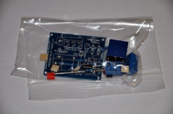
Fun and Simple Single Channel Relay Board DIY Kit
Control AC with Arduino
This listing is for a single channel relay board kit. It is easy to put together and easy to use. There are two on-board terminal blocks. One is used to power the circuit and control the relay, and the second houses the relay terminals. The circuit requires a 5v source. When the signal pin (SIG) receives a 5v signal, the relay turns on. As well, an LED indicator lights up to show you that the LED is on. Control 120 VAC appliances with this device, and control it with your digital 5v circuit! The shows you how to put it together from scratch, and how to use it. After we assemble the device in the video, we hook it up to an AC source, and use it to power a lamp. Seriously! Watch the video!
Here are the labels that are on the PCB for each terminal block:
For the power terminal block:
5V: This is where you connect your positive supply (5v source). It can be taken from your arduino or from a 7805 5v regulator.
SIG: This is your signal line. Feed this line 5v to activate the relay.
GND: This is your supply ground.
For the relay output terminal block:
NO: Normally Open connection. This pin is normally NOT connected to the COMMON (CO) pin.
CO: Common connection. This pin is connected to the NC pin when the relay is not active. It connects to the NO pin when the relay is active.NC: Normally Connected pin. This pin is connected to the CO (Common) pin when the relay is not active. When the relay is activated, this pin is no longer connected to the common pin.