|
|
The APR9600 Record and Playback DIY Kit
Record up to 8 Messages !
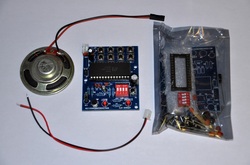
This listing is for an APR9600 based record and playback DIY electronics kit. We also sell these fully assembled for a few dollars more. This is a high quality kit, and it includes a power plug that fits directly on to the board, and a detachable speaker that fits on to an on board 2-pin header. It is pretty easy to put together, and I've created a video that can be seen above that shows you how to work the device, and how to put it together. The video offers step-by-step assembly instructions and several demonstrations. The kit comes with all that you need to assemble the device from scratch (All of the components talked about in the video). Please note that no hard copy of the schematic or instructions will be included. You can print the schematic diagram that is provided below, and the video acts as your instruction manual.
The kits are sealed in an ESD bag for protection, and the 28 pin socket and the 28 pin APR9600 DIP IC each rest in an ESD safe foam to protect the ICs from being damaged in transit. We are very proud of the quality of this kit. Below, you can find the schematic diagram. This board requires between 7VDC and 12VDC to operate. There is an on board 5v regulator IC that limits the voltage to the APR9600 (78L05).
You can also amplify the output volume of the APR9600 by interfacing it with an audio amplifier circuit. While said circuit does not come with this kit, we have small audio amplifiers and audio amplifier kits in our store that will work nicely.
THIS KIT COMES WITH:
1) A Custom PCB
2) All of the components required for assembly
3) A power connector that fits right into the board
4) An 8 Ohm 0.5W speaker that connects to the on board two-pin output header. This is convenient and can easily be detached.
DOCUMENTS:
Schematic Diagram: http://www.electroniclessons.com/APR9600.pdf
Component List: http://www.electroniclessons.com/Components.xls
APR9600 Data Sheet: http://www.8051projects.info/datasheets/APR9600.PDF
Please note that there are a couple of discrepancies between the parts list and the schematic. C10 in the schematic should be 10uf, and C2 should be 10uf. WE HAVE TONS OF OTHER REALLY COOL ELECTRONIC DIY KITS AND COOL ELECTRONIC COMPONENTS, SO CHECK OUT OUR STORE!
Watch the video. It will show you everything that you need to know. No hard copy instructions are included. Everything that you need is right in the video. The video is your instruction, and your functionality guide. Please do not hesitate to ask any questions you may have. We will answer them quickly!