|
|
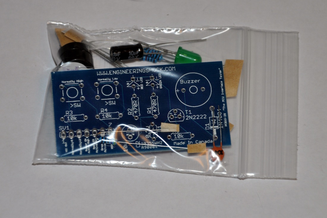
The Arduino troubleshooting board DIY electronics kit with LED & button & buzzer
This listing is for a DIY troubleshooting kit. When assembled, this board has three input indicators, and two output options. The input indicators are two LEDs; one green and one red, and a transistors activated 5v piezo buzzer. The output options are two buttons; one is normally high (5v) until pressed, at which point the output goes low (0v). The other button, which is normally low (0v) until pressed, at which point the output goes high (5v) until the user lets go. The circuit requires 5v to operate. There are 7x solder-able pads on the board; each of which are talked about in the video. The above video gives you a demonstration of each function, and also shows you how to assemble the kit. The video is your instruction manual when you purchase this kit.
When you purchase this kit, you will receive the circuit board, and all of the components required to populate it. The pads are labelled, but the text is very small. From the front left, to the right of the board, here is the order of the pads:
Leftmost
1) 5v (VCC)
2) Normally High Button Output
3) Normally Low Button Output
4) Active High Buzzer Input
5) Active High Red LED Input
6) Active High Green LED Input
7) Ground
Rightmost
If you have any questions, please do not hesitate to ask!