|
|
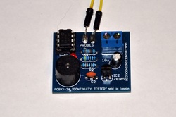
Continuity (short circuit) Tester DIY Kit
This listing is for a continuity tester kit that can be used to test circuitry for short circuits, and low resistances. It is very easy to put together, and the video above offers a full demonstration, and step-by-step assembly instructions.
Operation:
If the microprocessor sees less than 100 Ohms, but more than 2 Ohms of resistance between the two probes, then the on-board LED will flash. If the resistance between the two probes is more than 100 Ohms, then the module will offer no reaction at all. If there is a dead short between the two probes (<2 Ohms), then the device will offer a steady beep, similar to that of a continuity tester on a good DMM. There is a voltage divider made of up 2x 1k ohm resistors on the board. The middle of the voltage divider is connected to the analog-to-digital converter pin of the on0-board micro-controller. Then there is a dead short between the leads, there will be no voltage at the ADC line. The MCU is always scanning voltages at the voltage divider. When the probes are not connected to any load, the voltage at the divider is 2.5v. The schematic is available below in case you wanted to follow along. the MCU is finely tuned to react differently to different loads, which is why the kit is able to:
A) Not react to loads higher than 100 Ohms
B) Flash the indicator LED when resistances between roughly 2-100 Ohms is measured, to indicate a low resistance path.
C) Turn on the on-board buzzer to indicate that less than 2 Ohms is being measured between the two probes.
This Kit Includes:
1) A custom PCB (As seen in the below video)
2) All of the components necessary for assembly, minus the wires required for probes. All you need for probes are two pieces of wire.
Note: This kit DOES NOT come with any hard copy schematics or instructions. All you need is right here in this listing.
Requirements:
1) A 7-12v power source
2) A Soldering iron and solder
3) Soldering experience
4) Imagination!
Kit Schematic: http://electroniclessons.com/Continuity.pdf