|
|
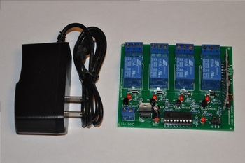
Four Channel Wireless Relay Board
with Momentary & Latching Modes + AC Adapter
This listing is for a four channel wireless relay board. This listing also comes with a keychain transmitter with four buttons (Corresponding to each relay), and an AC adapter. This device comes to you fully assembled, minus the adapter connections, which you do yourself based on the information below. The above video offers a full demonstration. We will also be selling this in DIY kit form for a few dollars less. We have tons of great electronic projects available, so make sure to check out our store!
OPERATION:
When you receive this board, the 9v AC adapter will have a 5mm jack on it. Cut the end of the jack off so that you only have a black wire. From there, strip back about an inch of the black insulation to reveal a smaller red wire, and a smaller black wire. The red wire is your positive 9v wire, and the brown wire is your DC ground wire. Strip back the insulation of the red wire to reveal the copper, and connect it to the "V+" terminal on the power terminal block. Then strip off a small amount of the black wire insulation to reveal the copper on the black "Ground" wire, and connect it to the "GND" terminal on the power terminal block. You can now plug in your device.
There are two programs that are available to you via the three pin header on the main board. Note that the three pins are labelled "LAT", "COM", and "MON". If you place the two pin header connector to short the COM/LAT pins, then when you power the device up, whenever you hit a transmit button on the transmitter, the corresponding relay will turn on, and stay on until you press that button again. This is called "latching". If you place the two pin header connector to short the COM/MON pins together and power up the device, it will power up in Momentary mode, which means that when you press a transmit button on the transmitter, the corresponding relay will activate, and stay activated until you let go of the button; at which point the corresponding relay will turn off.
The relays each have a three pin terminal block in front of them. Each terminal block has labels for each port of the relay: CO (Common), NO (Normally Open), and NC (Normally Closed). When the relay is not active, the common pin is connected directly to the normally closed pin. When the relay is activated, the common pin disconnects from the normally closed pin, and connects to the normally open pin. It is a high power switch. I designed the relay traces to be very thick, so that AC devices can be activated/deactivated very easily. If you wanted to connect a lamp for instance, the power line to a lamp should have three wires:
WHITE = NEUTRAL
BLACK =- HOT
GREEN = GROUND
If you cut the black (HOT) wire on the lamp power cable, you can connect one side of the cut wire to the CO pin, and the other to the NO pin. When the relay is activated, the common pin connects to the normally open pin, and re-attaches the black wire, and therefore completing the circuit. Alternatively, if you wanted power to be applied to the lamp and only have it turn off when the relay is activated, you can connect the one black wire from the lamp to the CO pin, and the other to the NC (Normally Closed) pin. Since the relay is off by default, the CO and NC pins are connected internally. When the relay is activated, the CO pin disconnects from the NCpin, and therefore opens the circuit, so no power will reach the lamp. I hope that makes sense =)
The receiver board which is located on the right side of the board should be able to detect the transmitter from about 25 meters away. Please note that you can extend the antenna on the transmitter to maximize this. However, you can also extend this distance by taking a thin single strand wire and looping it around a pencil 18-24 times, and soldering one end to the ANT (Antenna) hole on the upper right side of the receiver board. This should extend the receiving distance to around 50 meters, as long as the transmitter antenna is extended.
The transmitter has four buttons. If you watch the video above, this section will make more sense. If you are looking at the board from the front side (relays at the back/power lines on the front), the left most relay is relay#1, and the rightmost relay is relay#4. The transmitter buttons activate the relative relays in this order:
Transmitter Button (B) corresponds to RELAY#1
Transmitter Button (D) corresponds to RELAY#2
Transmitter Button (A) corresponds to RELAY#3
Transmitter Button (C) corresponds to RELAY#4
If you have any further questions about the operation, please do not hesitate to ask. If you want, I can modify the AD adapter prior to shipping for you, but you need to ask me before I ship =)
APPLICATIONS:
You can control up to four AC or DC devices with this set. It is very easy to operate. If you have a question relating to whether or not this device would fit your specific application, I'll do my best to answer any questions that you may have.
WHAT COMES WITH THIS SET?
1) One fully assembled and tested wireless relay board
2) A four button transmitter key-chain with extending antenna.
3) An un-modified 9v 1000mA AC adapter
SPECIFICATIONS:
Power Supply Voltage/Current: 7-9VDC @ >700mA
Main Board Length: 95mm
Main Board Width: 74mm
Main Board Height: 19mm
MOUNTING:
There are four mounding holes on this board. One in each corner. No mounding hardware is included.