|
|
The Forever Rechargeable Super Capacitor Flashlight Kit
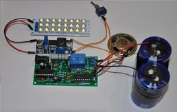
This listing is for a complete talking super capacitor flashlight DIY Electronics kit. It comes with a talking charger board DIY kit that charges two series 2.7v series super capacitors to roughly 5.33v. In addition, this kit includes 2x 400F 2.7v super capacitors, a power switch, a voltage booster, and a 24-LED bank! You build it yourself! We sell these kits in several different variations. When you plug the unit in, it tells you that the capacitor flashlight is charging. It tells you when the capacitors have reached 20%, 40%, 60% and 80% of total charge. Once charged, the device tells you that the capacitors have been successfully charged. If you watch the video above, you will see how you can use these parts to make your own super capacitor flash light. The video below is an assembly video instructable. This video offers step-by-step assembly instructions that function to show you how to interface your charger board with super capacitors, voltage booster, and an LED bank. Of course, you might have a completely different application for this unit. This video is there if you need additional information.
If you purchase this listing, you will receive the talking super capacitor flashlight charger board DIY electronics kit, an AC adapter, 2x 400f 2.7v super capacitors, a voltage booster, power switch, and LED bank. EVERYTHING YOU NEED ALL IN ONE! This board can not charge two series 2.5v caps. They must be 2.7v caps, as the device is programmed to charge two capacitors in series to 5.33v. The above and below videos will give you a complete demonstration of how the booster board works, and how you can put it together.
How it works all works:
The wall transformer acts to power the charger board, as well as to charge the capacitors. The charger board limits power to the super caps, and acts to turn the charge to the caps on and off, depending on the voltage detected on the caps. When you plug in the board, charging commences (See Video above or below). When the voltage on the caps reach roughly 5.33v, the charger stops charging the caps. The power on the caps can be access via the output terminal block. A switch is connected between the positive lead of the capacitor bank via the terminal block to the input of a voltage booster. This voltage booster needs to be calibrated to a voltage using an on board variable resistor. As long as there is at least 3.4v at the input of the voltage booster, then the output can boost to up to 34v. Make sure that before you connect the LED bank, that you tune the output to 8-12v. I suggest 9v (See Video Below). The LED bank is connected to the voltage booster output, where it receives power. When the switch is turned on, the capacitor voltage is connected to the booster voltage, which is then boosted to a higher voltage which can operate the LED bank. There is a memory chip that is used to store voice info that is triggered by the microcontroller during operation so that the device itself can talk to you.
Description of included Parts:
The talking super capacitor charger DIY electronics kit- This board serves to charge your capacitor bank up to roughly 5.33v. When you plug it in, the device tells you that capacitors are charging. When the unit is charging capacitors, the unit keeps you updated by telling you how far along the unit is relative to charge. When charging is complete, the red indicator LED starts flashing, and continues to flash until the user removes power. In addition, the board tells you every ten seconds or so that the capacitors are charged, so that you get an audio and visual indicator! Once the capacitors are charged, there is no back powering through the device. An internal relay separates the capacitor bank from the rest of the charger board circuitry. Once charged, the bank should stay charged unless it is loaded via the output terminal block.
9v 1000mA AC-DC Wall Adapter: This unit plugs into the charger board, and acts to both power the on board digital circuitry, but it also acts to charge the capacitors.
The Voltage Booster: This voltage booster can boost any voltage at the input between 3.4VDC to 34VDC. Meaning that if I have any voltage at the input betwen 3.4v-34v, then I can boost the output to anywhere in between. For instance, if I have 5v at the input of the booster, I can boost the output to anywhere from 5v to 34v. The higher the differential between the input and output, the lesser amount of current can be sourced. Luckily, all we want to do is boost the voltage on the capacitor bank to anywhere between 8-12V (8v is bright, but 12v is EXTREMELY bright. The advantage to using 8v on the LED bank is that the flashlight will last longer. To really understand how this works, please watch the below video in full. We talk a lot about this booster module, and I even show you how to calibrate it.
The Switch: This switch is merely an on/off switch that acts to apply power from the capacitors to the voltage booster, which powers the LED bank.
The LED bank: This little guy is BRIGHT! It emits light at voltages between 8-12VDC. It is pretty bright at 8v, but extremely bright at 12v! We're going to power this with the output of our voltage booster.
The capacitors: The 2x 400f 2.7v capacitors will be placed in series to make a 200F 5.4v bank. These will act as our battery bank!
We sell other variants of this kit, so check out what other options we have by going to our front store page!
Documentation!
This kit is semi-based off of an instructable that I wrote. It describes most of the theory behind this device:
http://www.instructables.com/id/The-Super-Capacitor-Flashlight-with-Custom-Charger/
Here is a demonstration of a fully build unit of my preliminary non-talking version with a housing (Housing, booster, switch. LED bank, and transformer not included with this listing):
http://www.youtube.com/watch?v=fbA7zx9149U
We also offer three other variations of this kit. Just check out our store!
1) We sell this charger board in DIY kit form for a few dollars less
2) We sell the entire electronics set fully assembled, and ready to be put into a fixture.
3) We sell the charger board fully assembled and tested.
Instruction/Assembly Video: