|
|
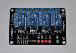
Active-Low Four Channel Relay Board
Control AC Devices with Digital Signals
This listing is for a 4-channel active low relay board. The the logic at a relative input pin is low (0v), the relay that corresponds to that pin will turn on. Each relay has a three pin terminal block that has a common pin (CO), a normally open pin (NO) and a normally closed pin (NC). By default, when a relay is not activated, the CO pin is connected to the NC pin. When the relay activates, the CO pin is no longer connected to the NC pin, but rather to the NO pin. The video above offers a full demonstration. The board requires 5v to operate. There are 6 pins, which are talked about below. There are four mounting holes; one in each corner,and the relays are rated for 250VAC 10A/30VDC 10A. Each board comes sealed in an ESD (Static Protected) bag. If you have any additional questions, please do not hesitate to ask!
The Pin-Out:
VCC- Connect 5v to this line. This is the power line.
IN1 - Input for relay#1. When this line is brought low (0v), relay#1 will turn on.
IN2 - Input for relay#2. When this line is brought low (0v), relay#2 will turn on.
IN3 - Input for relay#3. When this line is brought low (0v), relay#3 will turn on.
IN4 - Input for relay#4. When this line is brought low (0v), relay#4 will turn on.
GND - Connect your power supply ground here.