The HQ Record & Playback Audio Module Information Page
This page includes sample Arduino code, an assembly video, a comprehensive video manual, and a block diagram.
Sample Arduino Code (Commented):
| hq_record_and_playback.ino |
The Video Manual:
The Assembly Video:
The Block Diagram:
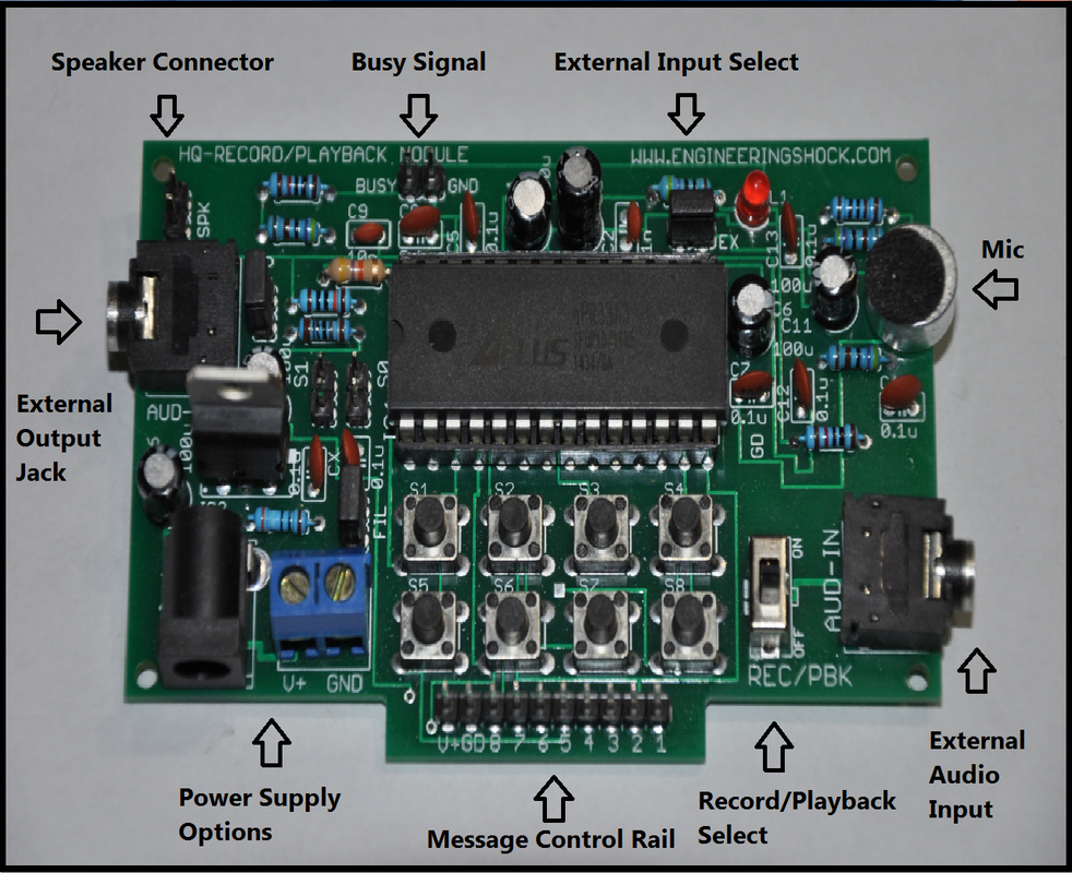
Power Supply Options: This unit requires 7.5v to 9v to operate. There is a power supply terminal block, and a 5mm power jack. The block has two terminals labelled "V+", and GND. Connect 7.5v-9v to the V+ terminal, and DC ground to GND terminal to power this unit. Alternately, some reward tiers include a compatible 9v 1A wall adapter.
Message Control Rail: To record and playback message using an Arduino, you will need this rail made up of a 10-pin male header block. This block contains a regulated 5v pin "V+", a DC ground connection "GD", and pins labelled 1 through 8. These pins control messages one through eight respectfully. Messages are played back when any of these lines are pulled low (OUTPUT,LOW). A code sample will be available at the end of this campaign.
Record/Playback Select: This switch allows for the user to select between record and playback mode. When the switch is in the "ON" position, then the user is in record mode. When the switch is in the "OFF" position, then the user is in playback mode.
External Audio Input: This stereo jack is where you would connect an external audio input source; say from your PC, or Mac.
Mic: This is the on-board microphone that can be used to record verbal commands, and the like. It can also be used to record what is going on in a room.
External Input Select: Using this jumper you can select between the on-board microphone, and the external audio input for recording. When the jumper is removed, you are only using the microphone to record. When the jumper is on, you can use an external audio source. You can also add in your own voice and have a karaoke effect when you use an external source, as the microphone is still connected. Please see the video manual for more information.
Busy Signal: This 2-pin header consists of an ground pin (GND), and a busy pin "BUSY". The logic on this pin is normally high (5v), and goes low (0v) when the unit is in the midst of recording, or playing a message back. Once this task is complete, the logic on this line goes back to 5v. This signal is useful when using a microcontroller to playback messages. The logic on this line is the inverse of the on board LED.
Speaker Connector: This 2-pin header connects to the speaker attachment.
External Output Jack: If you wish, you can use this jack to connect the audio output to an external amplifier/speaker set for higher volume. If you choose to do this, simply remove the speaker, and connect to a set of computer speakers or audio input to your Bose player!
There is an on-board BUSY LED, and there are a few headers that allow for you to customize operations that are not labelled in the above diagram, but are talked about in the video manual.