|
|
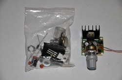
LM317 variable power supply kit DIY + Video Instruction
This listing is for an LM317 variable power supply DIY kit. This kit was designed so that you can have DC at the input, or AC (up to 36VAC from the secondary of a transformer), or 36VDC). It was built initially for AC, but you can use it just as easily for DC. If you look at the enclosed schematic, you'll see the build of the LM317 circuit. You can bypass the bridge rectifier and use DC, or use the bridge rectifier with AC. This kit does not come with any formal instructions. We received them recently, and they came with nothing WHICH IS WHY I CREATED THIS VIDEO SO THAT YOU CAN FOLLOW ALONG WITH ME IN BUILDING YOUR KIT! The video below is the only form of instructions. It is a very easy kit to put together, but you have to follow along with the video. If you have any issue following along with the video, please don't but the kit. I made the video to be as straight forward as humanly possible.
This kit includes:
The PCB
All the parts required shown in the video
The video in this listing is the instructions.
This kit, when assembled is rated for a maximum of 36 VAC at the input. I wouldn't surpass 30VAC myself, but you have the option. Of course, most of you are going to want to have DC at the input. You now have a ton of options. Let's say you are wanting to use a DC input source. You can still solder to the AC input holes, and it won't matter which AC input you use for DC+ or DC-, as the bridge rectifier will allow for this. However, if you do this, you're going to have voltage drops across two diodes. That's not cool. The best way to have DC at the input is to solder to the +DC-IN pin for the positive DC (RED) pin, and the -DC-IN pin for the negative DC input wire (BLACK). Confused? Watch the STEP-BY-STEP VIDEO!You can have 36VDC at the input MAX. Output current MAX is 1A. We also sell these in DIY kit form, but I have to re-create the kit instructions, as no instructions were included when we purchased them.