The LoRa KitProject Page!
Thanks to the Kickstrarter pledges who made this campaign possible. This page will be updated periodically with new information. Stay tuned. A couple of things to start. You'll need to click on the link below for instructions on how to get your LoRa kit up and running. The Heltec LoRa module (V2) requires some actions to get up and running.
QUICK START INSTRUCTIONS:
Read this document. It is easy to follow and is hugely important! docs.heltec.org/en/node/esp32/quick_start.html
That document shows you how to install the driver, and how to get your Arduino working with the Heltec modules. You don't need to worry about Git. I certainly didn't. One thing that I'll mention is that if your Arduino isn't up to date, get the latest version. As well, if you get compiling errors, you've done something wrong. I've made this mistake, so trust me. Follow the instructions in the above document, and then try compiling one of the code samples below. If they compile, then you're on the right track. If there are compiling errors, then you've made a mistake somewhere.
Getting Started!:
When you receive your LoRa kits, watch this video to show you hot to put everything together:
Sample Code:
Below you'll find all of the sample code. For every project there is a TX (Transmitter) code sample, and an RX (Recieve Code sample). As the project videos are created, they'll be listed below. There will be one for every project. Make sure that you have one LoRa kit with TX code uploaded on it, and one LoRa kit with the RX code installed on it.
Project#1 - Learn to transmit from one LoRa kit to another!
| lora_ks1_tx.ino |
| lora_ks1_rx.ino |
Project#2: Addresses! Use the TX to send to all addresses sequentially. If an RX unit with matching address in range, then the RX unit will act accordingly to your code. RX: "Only execute code if the address transmission that I've received matches my own address!"
| lora_ks2_tx_addresses.ino |
| lora_ks2_rx_addresses.ino |
Project#2: ACK! - The transmitter sends out all address values (1 to 10). When the receiver receives the address transmission that matches it's own address, then it will send back an ACKNOWLEDGEMENT, which is then received by the transmitter.
| lora_ks3_tx_sendback.ino |
| lora_ks3_rx_sendback.ino |
Project#4: Data Sampling! The receiver (RX) waits for noise detection. If a loud noise is detected, it sends an alarm to the TX, along with it's address.
| lora_ks4_tx_sampling_data.ino |
| lora_ks4_rx_sampling_data.ino |
Project#5: Lights OM! Lights OFF! - In this project, the RX will sample the room light every 5 seconds, and then send light data back to the TX for decoding.
| lora_ks5_tx.ino |
| lora_ks5_rx.ino |
Project#6: Motion Sensors! - In this project, the receiver acts as a motion sensor. It waits for motion after a stabilization period. If motion is detected, it sends back an alarm to the TX and includes it's address, which means that the TX can display which room detected motion.
| lora_ks6_tx_motion_sensor.ino |
| lora_ks6_rx_motion_sensor.ino |
Project#7: CALL AND ANSWER! - This project builds off of project#3 and project#6. The TX will query each RX address. If the RX with the matching address is within range, it will send back motion sensor data. If motion has been detected since the last communication, the RX will send back an alarm. This project is different, and it is an important one. This project shows you how to use the transmitter to question each RX individually. Why is this important? This is so that RX units don't all transmit at the same time. That would confuse the transmitter, and packets would get lost in limbo. If the TX is in control of asking questions o the RX, then you won't lose packets. In other words, data won't get lost.
| lora_ks7_tx.ino |
| lora_ks7_rx.ino |
Project#8: The Combination Lock! - You'll need some of your own hardware for this project, but we're going to use the TX as a combination lock, and the RX as a receiver/electromagnetic lock driver.
| lora_ks8_tx.ino |
| lora_ks8_rx.ino |
Supplementary Content:
In this section, we'll discuss the buzzer, level shifter, LED, and ADC pins and Bluetooth!
The Active Buzzer:
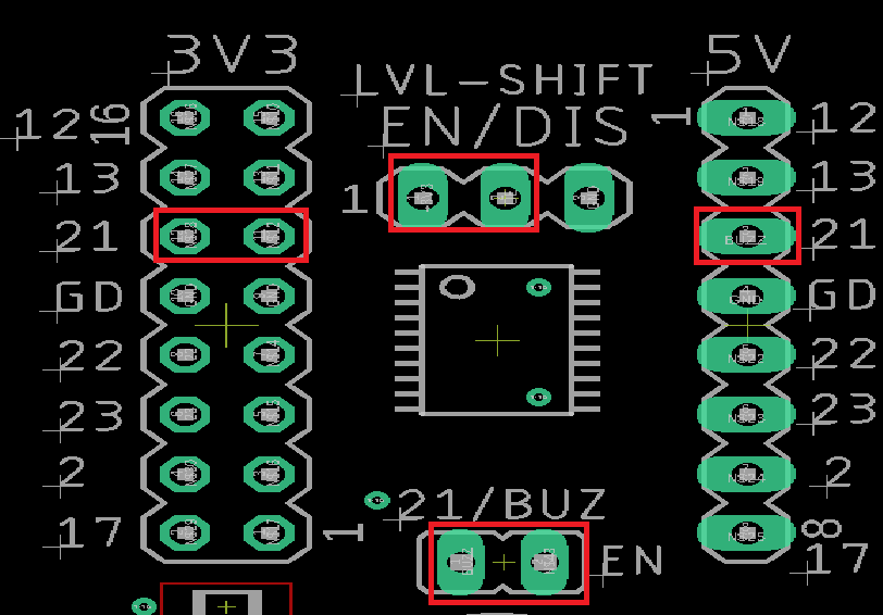
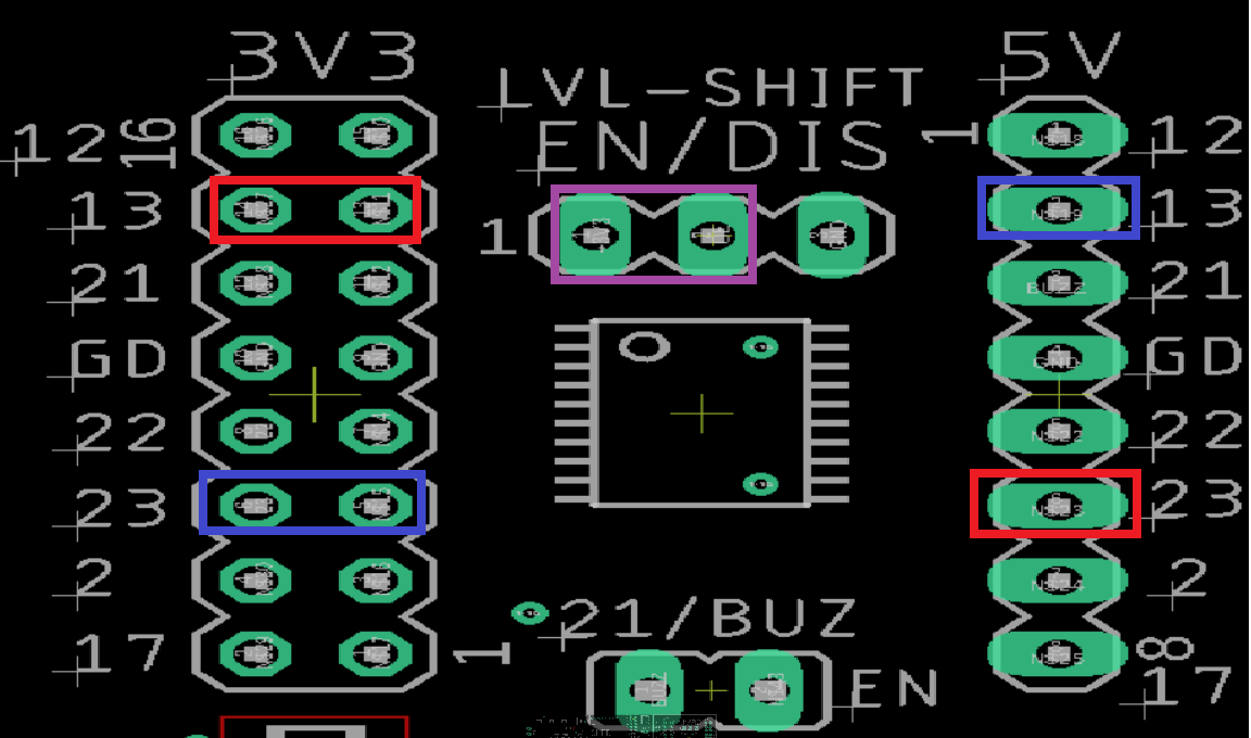
The active buzzer can be implemented quite easily. To do this, need to set GPIO 21 as an output, and connect a jumper to the GP21 level shifter pins on the left-hand-side of the picture below. From there, connect a jumper to the '21 BUZ EN" pin header. Lastly, place a jumper on the "EN" side of the "EN/DIS" header to enable the level shifter. Now when you set GP21 high, the buzzer will turn on. Then buzzer will turn off when set to LOW. The 5v side of the level shifter (21) will reflect the HIGH/LOW logic on the buzzer driver: 5v when high, and 0v when low.
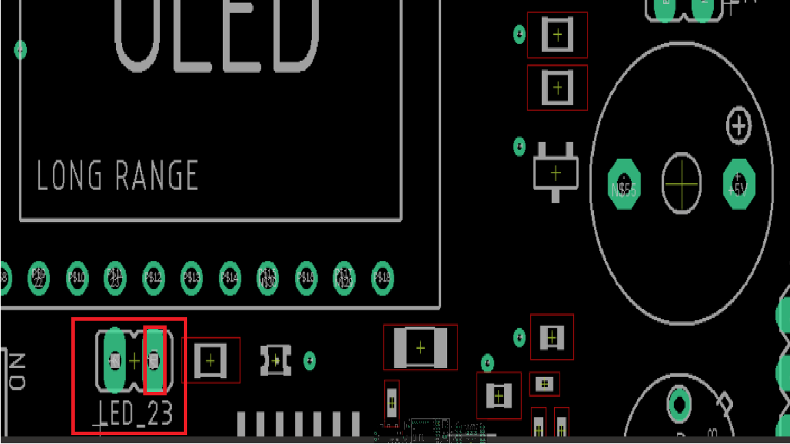
The LED:
If GPIO#23 is set as an output and your have a jumper on the LED_23 jumper, then the LED will turn on when GP23 is set to high, and turn off when set low. If you don't want to use GP23 to control this LED, you can use a wire connector to jump the right pin on the LED_23 pin head to the signal line that you want to use as an indicator. GP23 is connect to the left pin of the header, and the LED circuit is connected to the right.
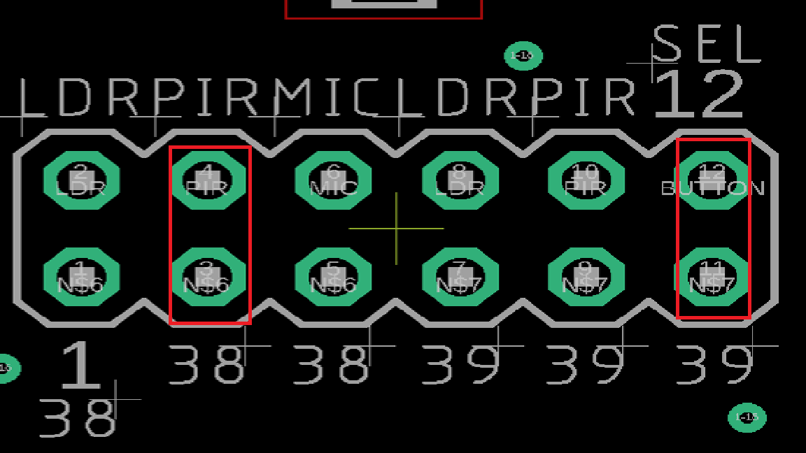
ADC Pins 38 and 39!
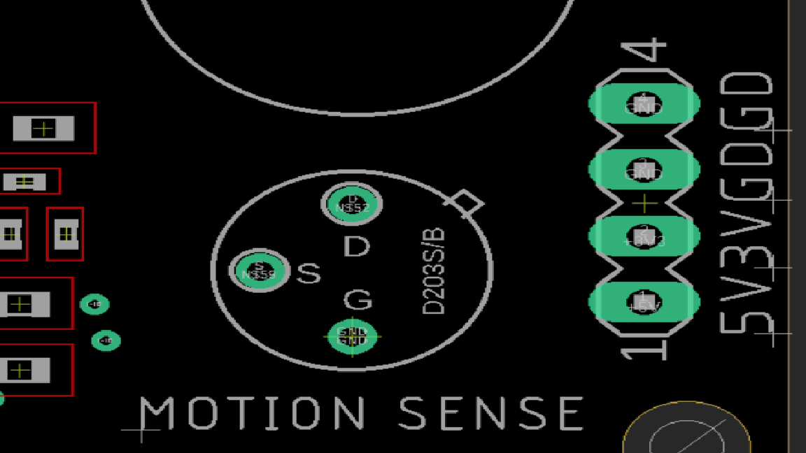
There are two available ADC pins available for use (ADC pins 28 and 39). ADC pin 36 is fixed for ADDRESS SELECTION, and ADC pin 37 is fixed for the keypad. When you're using AD pin 38, you can select between the LDR (Light sensor), PIR (Motion sensor), and the microphone (MIC). In the image below, we have the PIR motion sensor connected to ADC pin 38. You can only have one item connected to each of these ADC pins. ADC pin 39 has three options as well, and can connect either to the light sensor, motion sensor, or SEL switch. In the example below, ADC pin 39 is connected to the SEL button.
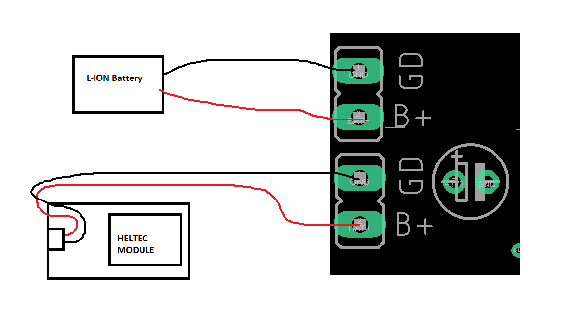
Battery Connector:
On the underside of the HELTEC board there is a battery connector. A battery connector cable comes with each HELTEC module. Plug it in before you connect the HELTEC board to the LoRa kit board if you'd like to use the battery function. IF you want to add in a battery, here are the instructions.
1) Connect the battery connector cable to the underside connector on the HELTEC board.
2) Solder the red wire of the connector to the lower "B+" pad. Solder the black wire to the lower "GD" pad.
3) Solder the positive (RED) wire of your 4.2v Lithium-Rechargeable battery to the upper "B+" pin. IT IS EXTREMELY IMPORT THAT IF YOU ARE GOING TO USE THE BATTERY OPTION THAT YOU USE A LITHIUM-ION 4.2V B ATTERY. ALL OTHER BATTERIES ARE INCOMPATIBLE AND WOULD BE DANGEROUS TO PLACE IN THIS CIRCUIT. You can solder in a switch between the red positive wire of the battery and the "B+" pad if you'd like to add in an on/off power switch to connect and disconnect battery power.
4) Solder the black wire of your Lithium-ION battery to the upper "GD" pad..
The HELTEC board has a battery charger circuit on it that can charge a 4.2v lithium-ion battery at 100mA. It is a slow-charger, but it works great!
The Level Shifter:
The level shifter allow for the HELTEC board to communicate with 5v compatible devices, like Arduino. An Arduino board outputs 0-5v signals, but it can access 3.3v and 5v signals. Look at the image below. As you can see, we've enabled our level shifter by adding a jumper to "EN" on the LVL-SHIFT EN/DIS" header (Purple). Here are two examples:
1) GP13 on the Heltec board is set as an output. We want to send a 5v signal to an Arduino. Place a jumper (red) on the two 3V3 GP13 pins. This connects the GP13 Heltec board pin to the level shifter. If you want access to the GPIO pin itself, you can add a wire connector to the left pins on the 3V3 header.
Now that we've enabled our level shifter and connected GP13 to the level shifter, when we set GP23 high in our program, the '13' pin (blue) on the 5V header will read 5v instead of 3.3v. It will read 0v when GP13 is set low.
2) We want use an external Arduino to send a signal to the Heltec GP23 pin, which is set as an input. Connect the external signal to the '23' pin on the 5V header (red) and connect a 2-pin jumper to the GP23 pins on the 3V3 header blue). You need to make absolutely certain that GP23 on the Heltec board is set as an input for this to work. When the external signals is set to 5v, GP23 on the HELTEC board will now see 3.3v. When the external signal is LOW (0v), the input on the Heltec board will see 0v.
KEEP IN MIND THAT EXTERNAL CIRCUITS NEED TO SHARE A DC GROUND CONNECTION WITH THE LORA KIT! You cannot share signals with external board if the HELTEC DC ground connection isn't connected to the external circuit's ground connection. Please see the 'Power Connector" section below.
Power Connector:
The external power connector allows for you to power small external circuits, and/or connect to them by sharing a common DC ground connection. There are four pins:
1) 5V - This is a regulated 5v connection. Do not pull more than 75mA from this line. It was not designed to provide a lot of power.
2) 3V - This is a regulated 3.3v connection. Do not pull more than 50mA from this line. It was note designed to provide a lot of power.
3) GD & GD - These are DC ground connection points.
Hardware Discussion:
This video talks about all of the above functions in more detail!
Getting Ready For Bluetooth!
Download the free version of the RoboRemo app on the app store. You can pay a small fee for some extra functionality if you'd like. In this video, I provide some basic instructions on how to use your smartphone to communicate with the LoRa kit! Please note that while this is a relatively simple task all around, you should consider doing the projects above before playing with this function.