|
|
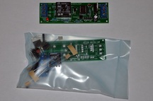
Customizable Relay DIY KIT
with Toggle Option & Active High/Low Settings
This listing is for a customizable single channel relay driver board DIY electronics kit. Using only one header connector, you can choose the trigger to be active high, active low, or toggle. It requires 7-12 volts to operate. There is a step-by-step assembly video below. To trigger an operation, there is an input signal line labelled "SIG". This is TTL (5v) compatible. No more than 5v should be applied to this line. This makes it easy for you to interface with your Arduino, TTL project, Basic Stamp, ARM or PIC project. This kit comes sealed in an ESD bag, and includes all of the components necessary for the build, including a single header connector. No hard copy of the instructions is included. Please reference the video below. We also sell these fully assembled and tested for a few dollars more. The video above offers you a view of what the final project should look like. The below information talks about the different operations you can choose from. You can not make changes on the fly. When you power up, depending on how you have your header connected will determine your mode of operation until you power off and on again. The colour of the relay may vary. It may be blue or green. Just an FYI =) Control your low power AC devices, or DC actuators today! If you have any questions at all, please do not hesitate to ask!
Operation Option#1 (ACTIVE-LOW)
If you place your header connector on the header marked "LOW", then the relay will be ON when there is 0v at the SIG (Signal) input, and LOW when you place 5v on the SIG (Signal) input. This is the ACTIVE-LOW Option.
Operation Option#2 (ACTIVE-HIGH)
If you make no connections to either the "LOW" or "LAT" connectors, then you are in the default mode, which is ACTIVE-HIGH mode. When you place a 5v signal on the SIG line, the relay actives and will stay activated until the voltage at the SIG line goes low (0v).
Operation Option#3 (LATCHING MODE - The Coolest Mode!)
If you place your header connector on the "LAT" header (Stands for "latching"), then every time the device receives a pulse at the SIG line, the output will toggle. When you first power up the device, the relay is off. After a single pulse is pulsed to the SIG line, the relay turns on and stays on until another pulse triggers the relay to toggle off. This is my favourite mode, and I think that it is likely the most useful mode. Please watch the videos for a demonstration.
Requirements:
1) 7-12VDC for power.
2) Signal Input "SIG" is rated for digital 0-5v signals.
3) Some soldering experience/DIY kitting experience!
Pinout:
1) V+ = Positive Power Supply Pin
2) SIG = Signal Input
3) GND = DC Ground
4) NC = Normally Connected To Common Relay Pin (Normally Closed)
5) CO = Common Pin
6) NO = Normally Unconnected To Common (Normally Open)
WARNING:
If you are going to be connecting 120VAC or higher to the relay, and you don't know what you're doing, make sure that someone is with you who can offer you some safety tips. high voltage can kill you easily, and I won't be held responsible if you hurt yourself. You have been warned =)