The Arduino Epoch Project Page!
|
|
The Epoch Learning Center (Complete Set) - Price includes tracked shipping to Canada & USA
$
260.00
Hi everyone. Thank you for visiting the Arduino "Epoch" Project page! This project library will be updated from time to time with new content, so feel free to come back here anytime! If you have purchased an Epoch set, watch the below "Getting Started" information!
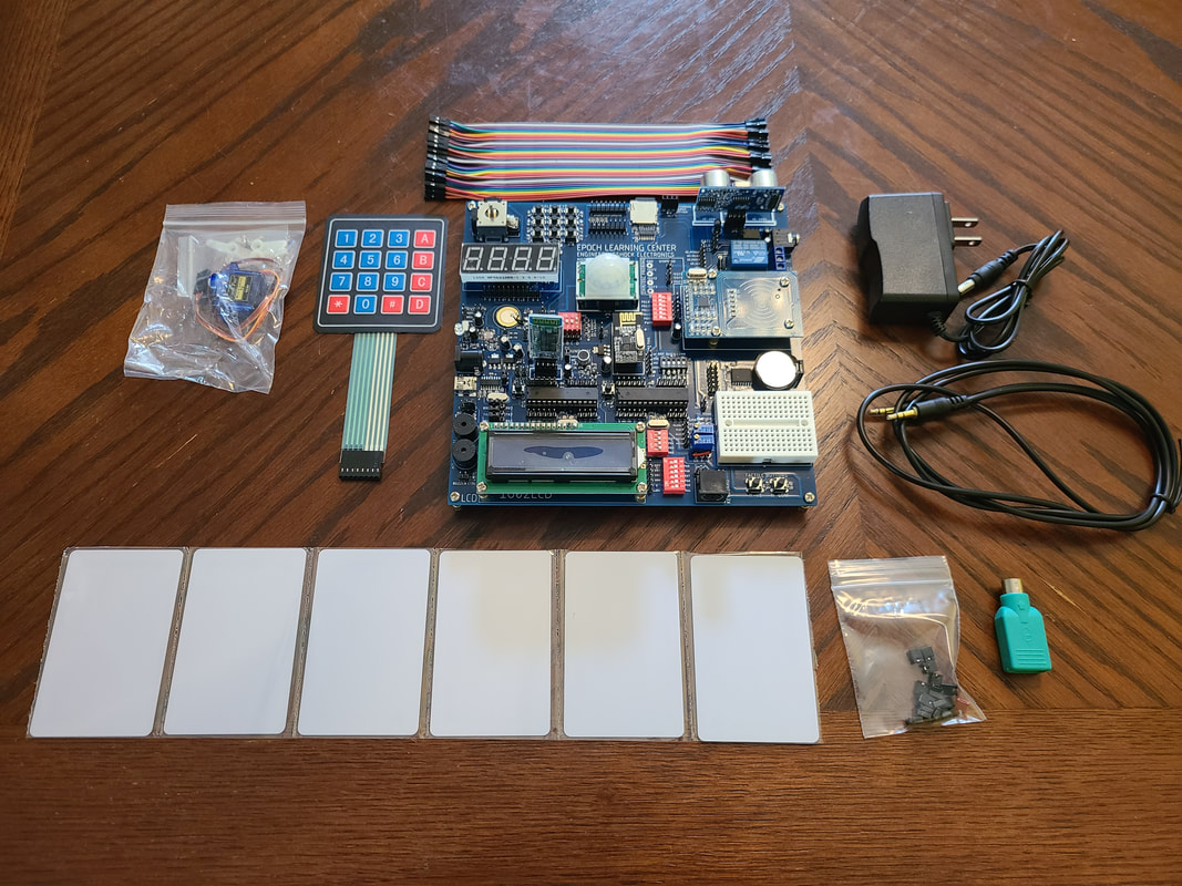
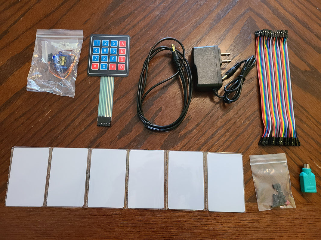
When you purchase an Epoch Learning Center set, you will receive:
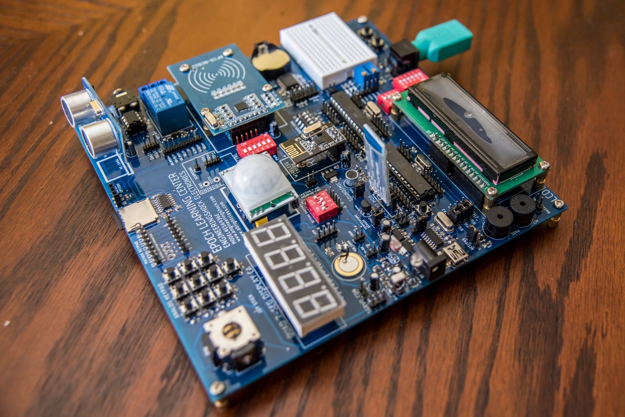
1x Epoch Learning Center Circuit Board (Completely populated with everything seen in the introduction video below)
1x 1602 LCD
1x RFID MFRC522 reader module
6x RFID cards
2x NRF24L01+ trancievers
1x HC-01 Bluetooth module
1x HC-SR04 Ultrasonic range finder module
1x PIR motion sensor
20x Male to Female cable connectors
20x Female to female cable connectors
1x AC-DC Power supply (9v)
21x M3 screws
13x 12mm stand-offs
1x PS2-USB Keyboard adaptor
1x USB cable
1x NRF24L01+ Arduino shield
1x 16-digit matrix keypad attachment
1x Stereo cable
1x Servo motor kit
TO BE USED WITH ALL OF THE PROJECTS BELOW!
What is the Epoch Learning Center? See it in action! Here is the video that was used in the Kickstarter:
When you purchase an Epoch Learning Center set, you will receive:
1x Epoch Learning Center Circuit Board (Completely populated with everything seen in the introduction video below)
1x 1602 LCD
1x RFID MFRC522 reader module
6x RFID cards
2x NRF24L01+ trancievers
1x HC-01 Bluetooth module
1x HC-SR04 Ultrasonic range finder module
1x PIR motion sensor
20x Male to Female cable connectors
20x Female to female cable connectors
1x AC-DC Power supply (9v)
21x M3 screws
13x 12mm stand-offs
1x PS2-USB Keyboard adaptor
1x USB cable
1x NRF24L01+ Arduino shield
1x 16-digit matrix keypad attachment
1x Stereo cable
1x Servo motor kit
TO BE USED WITH ALL OF THE PROJECTS BELOW!
What is the Epoch Learning Center? See it in action! Here is the video that was used in the Kickstarter:
The Epoch Learning Center!
Unboxing and Getting Started:
Getting Started! Follow these instructions!:
1) You'll need to download the CH340G drivers from github in order for your computer to communicate with the Epoch. Find it here: github.com/HobbyComponents/CH340-Drivers
2) Download Arduino IDE here: www.arduino.cc/en/software
3) Watch the above video! The most important details lay within!
4) When you're not using your Epoch, power it off unless you're data logging. This is to protect the board from brown-outs.
5) If you are using the AC-DC wall adaptor to power the Epoch as opposed to USB, make sure you use a surge protector/UPS.
The Little Buddy Talker Library:
The little buddy talker is a little chip that has 254 audio words and sound bites stored on it. I designed the Epoch with one! The current library is below.
| epoch_lbt_lookup_table___library.xlsx |
Epoch Little Buddy Talker Library Video:
Code Samples:
You'll be able to download project .ino files here! Here is a small taste. As you can see, the first 5x projects are small, and build from each other. These five projects are very simple, but act to show the user the basic formatting of basic code.
Project#1 "Wiggle your Big Toe!" - Upload this file to your Epoch and follow the setup instructions in the code to flash an LED on and off. When you've successfully done this, you are on your way! Let's get all these other piggies wiggling!
| epoch_flashing_led.ino |
Project#2 "Inputs and Outputs" - Building off of project#1, we'll now connect a normally-low push button, and flash the LED on and off only when the button is being held down!
| epoch_inputs_and_outputs.ino |
Project#3 "Inputs and Outputs and the FOR loop!" - Building off of the previous two projects, we'll now introduce the FOR loop, which helps us to achieve the same task numerous time using only a tiny bit of code. Flash the LED on and off 5 times when the button has been pressed!
| epoch_inputs_and_outputs_and_the_for_loop.ino |
Project#4 "Inputs and Outputs with the WHILE Loop!" - Building off of the previous three projects, we'll now use a WHILE loop to ensure that the LEDs flash 5x times only when the button has been pressed, and let go. If you press the button, nothing will happen until you let go. The WHILE loop acts to stall the program here!
| epoch_inputs_and_outputs_3_with_while_loop.ino |
Project#5 "Inputs and Outputs with Functions!" - With all that we've learned to this point, we'll now break the code down into reusable functions. Functions are subroutines that can be called on as many times as you'd like. When we call a function, it executes the code within it, and then returns to the area of code from where it was called from. Functions are your best friend!
| epoch_inputs_and_outputs_4_with_functions.ino |
Project#6 "Analog Inputs, Integers, and the Serial Monitor!" - We're going to save sensor data in a storage register (an integer), we';; learn how to use the serial monitor and discuss the output of the light sensor. See the project#6 video below.
| epoch_analog_inputs__integers__and_the_serial_monitor.ino |
Project#7 "The Light Sensor and the Relay!" - We're still using the light sensor and serial monitor, but practice is always a good thing. We'll use the light sensor to turn a relay on and off. We'll also talk about how the relay itself works. See the project#7 video below. A relay is a high power switch that is digitally controlled, but isolated from the rest of the electronics.
| epoch_the_light_sensor_and_relay.ino |
Project#8: "The Temperature Sensor and the LCD" - In this project, we'll learn about how to set up and write to the 1602 LCD, how to sample the temperature sensor analog voltage, how to average several measurements, and how to convert it into Degrees Celsius. This is a step up from the last project, but this is a useful one. Play around with some of the settings. Make sure to experiment with the code. Remember, you can always come back here and download the code again if you need to! Check out the project#8 video!
| epoch_the_temperature_sensor_and_the_lcd.ino |
Project#9: "The Passive Infrared (PIR) Motion Sensor" - This project is quite simple. It is actually quite a little bit simpler than project#9. We're going to play with the PIR motion sensor, and get a little more LCD practice in here. Later on, we'll make a Halloween themed prank project! If you're yearning for more complicated projects, you're in luck, as they are on their way. The goal is to do small projects in the beginning, and once every electronic block has been covered, we'll start doing some really fun projects! Anyhow, have a look the code and scroll down to see the project#9 video!
| epoch_9_the_passive_infrared__pir__motion_sensor.ino |
Project#10: "THE EPIC FART MACHINE PRANK" - We'll use the LCD as a countdown timer, and we'll use the motion sensor to tell us when to play a fart sound effect when people walk by. Take a look at the code, but for a proper demo, see the Project#10 video below. This is a fun one, and you can customize it as you'd like. Remember to play with the code. Don't just copy and paste it. Get a feel for it. Tinker with it. You can always come back and re-download it if you'd like! The best thing that you can do to learn, is to experiment!
| epoch_motion_sensor_far.ino |
Project#11: "Variable Delays with Variable Resistors" - In this video we'll get more practice with the Little Buddy Talker chip. We'll also use the analog pins to sample the output of one of he variable resistors (potentiometers). We'll use the data taken from the POT as a value in milliseconds for a custom delay time in between when sound bites are played by the Little Buddy Talker. See the project#11 video below!
| epoch_11_variable_delays_with_variable_resistors.ino |
Project#12: "The 7-Segment Display" - This project outlines the process of how to control a 7segment display using 9 GPIO pins. Make sure to check out the video, as it talks about the electronics within each segment. The code challenges you to make some changes to the software for the sake of experimentation. Make sure that you try it out!
| epoch_single_7_segment.ino |
Project#13(a) - "Multiplexing the 7-Segment Display!" - In this video we will learn how to make a countdown timer. We also learn how to Multiplex the 7-segment display. The code in this project is a little complicated, so take your time when reading it. Make sure to manipulate how the display works. Make changes to the code! See the project#13 video below. Don't forget to check out project#13(b), as it is related!
| epoch_project_13_multiplexing_the_4_digit_7_segment_display.ino |
Project#13(b) - "Multiplexing the 7-Segment Display with Variable Delays!" - The setup is the same as project#13, only we're going to use a variable resistor (POTA) to determine the delays between segment switching. This project is also covered in the project#13 project video below!
| project_13b_multiplexing_the_7_segment_display_with_variable_de.ino |
Project#14 - "Getting Started with the Analog Keypad!" - The Analog keypad is a beast. Using only one analog pin and some simple software, we can create a fully functional keypad. Each of the 10 buttons is connected to a section of a resistor-based voltage divider, which means that every button will provide a different voltage to the ADCK pin (See the project#14 video below). We'll sample that voltage, decode it, and print it to the LCD. The next project will include EEPROM memory and a combination lock!
| epoch_14_getting_started_with_the_analog_keypad.ino.ino |
Project#15 - "EEPROM & Combination Lock!" - Boy howdy, this is the most fun project thus far. In this project, we'll learn about how to read and write to EEPROM memory (Memory that is saved to the chips internal memory even after power off). We'll also create a four digit combination lock! Make sure to watch the project#15 video below.
| epoch_15_test.ino |
Project#16 - "The Ultrasonic Range Finder" - This is a very simple program. We'll learn how to use our HC-SR04 ultrasonic range finder to measure distance. We'll print out our results on the LCD. This is a little bit of a break after the more complicated project#15. Have a gander at the project#16 video below!
| epoch_16_the_ultrasonic_range_finder.ino |
Project#17 - "Plotting Audio Waveforms!" - In this project, we're going to sample the microphone/amplifier output and create a waveform out of it with the Arduino plotter. We'll also look at the serial monitor to see how volume changes the sampling data. Make sure to read the notes section at the bottom of the code. There are some fun things to try. This is a very simple project. Once you've tried it out, try re-writing the code without looking at the original copy. Remember, practice will help you to memorize the coping commands. Happy coding!
| epoch_project_17_plotting_audio_waveforms.ino |
Project#18 - "Receiving and Transmitting IR Signals" - This project is a little more complicated, as the IRremote library (Which you might need to download from github) has some hard to decipher requirements. With that said, I think that there's enough commenting to get by here. In the video, I'll show you the Infrared (IR) receiver output signal on my oscilloscope, as well as the re-transmitted signal from the IR transmitter LED. In the notes section of this code, I talk about making this project your own. Try to take what you've learned to change this project around so that an environmental effect triggers the re-transmission of the IR signal (Motion, light change, sound, etc). Make a good prank device with this bad-boy. What we'll do is receive a signal from a TV remote, and re-transmit that saved signal when we press any button on the analog keypad.
| epoch_18_receiving_and_transmitting_ir_signals.ino |
Project#19 - "Hard Reset with Analog Pins" - There are many ways to reset your Arduino, but I discovered this method for myself. This is not to say that this isn't a common practice. I just happened upon it one day, and it is a very useful method of causing a hard reset with analog pins. In this project we display a count on the LCD. It keeps counting up and up and up. However, if the noise in the room is too loud, the software causes a reset. How? We connect the A5 analog pin on Chip-A to the RST (Reset) pin on chip-A, which is pulled to 5v through a 10k resistor. When we use a command that changes the A5 pin from an analog pin to a digital pin, it causes the A5 pin to pull the reset line to 0v for an instant, and that causes a hard reset. This may not sound like fun, but I love this project. Play around with it!
| project_19_hard_reset_with_analog_pins.ino |
Project#20: "Active and Passive Buzzers!" - In this project we'll experiment with both the active and passive buzzer. Watch the project#20 video for a longer explanation. We'll use the analog keypad to send two different programs to the buzzer. Use the buzzer selection jumper on the Epoch to select between the two buzzers. The active buzzer has an internal oscillator which makes a consistent sound when powered by 5v. The active buzzer is more like a standard speaker. You need to pulse different frequency signals to it to create varied sounds. We make a police siren in this project! Check out the TONE.H library if you don't already have it. It can be found on github!
| project_20_active_and_passive_buzzers.ino |
Project#21: "The Voltmeter" - We're going to use the LCD, the test area, and one of the variable resistors (POTA or POTB) to create a voltmeter. This is a fun one, and very simple. We'll compare our Epoch voltmeter to a hand-held voltmeter for comparison with the help of the test area on the Epoch!
| epoch_21_voltmeter.ino |
Project#22: "Software Sabotage" - I don't know why exactly, but this is one of my favorites. I'll let the video do the talking. You're going to want to see this one. There is a fun and slightly difficult challenge in the notes section of the code. Watch the video, and look at the code. See if you can figure it out!
| epoch_22_software_sabotage.ino |
Project#23: "The PS2/USB Keyboard" - This is another simple one. Have you ever wanted to incorporate a computer keyboard into your electronics projects? Learn how with this simple project! This program will work with PS2 keyboard, and most USB keyboard with the help of the included adaptor. See the project#23 video below!
| epoch_23_the_ps2_usb_keyboard.ino |
Project#24: - The Real Time Clock (RTC) - In this project, we'll play with the DS3231 RTC module. We'll program it with the current time, then ask it for the updated time every three seconds. Each time, we'll print the time data to the serial monitor. The DS3231 chip also has an internal temperature sensor which we'll also use. There's a fun challenge in the notes section of this project. Make sure to check it out!
| epoch_24_rtc.ino |
Project#25 - The Matrix Keypad - The included 16-digit matrix keypad requires 8 GPIO pins. Lots of code too. Remember project#14? I do! While I'm not fond of Matrix keypads, it is important that you know how they work, and this code should give you a good idea. Matrix keypads are used everywhere. There is one challenge at the end of this code, and that is to use a library to shorten the code. I do not use a library, as I want to code it all out so that you can see how it works.
| epoch_25_matrix_keypad.ino |
Project#26 - Servos and Joysticks - Let's use the joystick to control either one or two servo motors. The code is too simple, but if you find that I confused you with the video, please consider looking at the notes section at the bottom of the code. The challenges there are really good, and I hope that you'll try them. I want you to see with your own eyes what the outputs of the vertical and horizontal joystick pins look like from an analog to digital perspective. Use the serial monitor. If you decide to try my combination lock challenge, then please consider making and sending me a youtube video. I want to see what you guys come up with!
| epoch_project_26_servos_and_joysticks.ino |
Project#27 - Data Logging - If you haven't done project#24, then please make sure that you do before going onto this project. We basically import and modify a lot of project#24 for this project, so heed my warning! We're going to use the SD card, PIR motion sensor, two LEDs, the state DIP switch, the RTC and the SD Card slot to log the date, time, and temperature to the SD card when motion is detected. There's lots to talk about here. Watch the project#27 video below!
| epoch_project_27_data_logging.ino |
Project#28 - EARTHQUAKE DETECTOR! - Let's learn how to use the vibration sensor to detect when an earthquake occurs! Warning, this is an easy project. The only new thing that we're talking about in this project is the vibration sensor. Make sure to watch the project#28 video below!
| epoch_28_earthquake_detector.ino |
Project#29 - NRF24L01+ Wireless Communications - Lots to learn here. Load the transmitter code into the shield, and the receiver code into the Epoch. Start with the transmitter code, as it is more complicated. Once you have read the transmitter code, the receiver code will be a little easier to follow. We're going to transmit two pieces of information from the shield to the Epoch, and use the serial monitor to read the received values from the Epoch. One piece of information being sent by the transmitter is fixed at a value of 8. I did this just because. The value of the other piece of information "address" will depend on your DIP switch settings. Confused? Watch the project#29 video! =D
Load this transmitter code into your shield:
| epoch_project_29_real_nrf_tx.ino |
Load this receiver code into your Epoch:
| epoch_project_29_real_nrf_epoch_rx.ino |
Project#30 - RFID - In this project, we'll learn how to save 5x cards into EEPROM memory, and then differentiate between these cards, and reject others. There are logs of fun challenges in the notes section of this code, so give them a try. If you run into trouble, don't worry. These challenges might be a little complicated at this point, and I'll cover them at some point. Remember, keep practicing. Keep trying. There's nothing better than the feeling of success after failing several times. I've been there hundreds of times over the years, so take heart if you do not succeed right away.
| epoch_project_30_rfid.ino |
Project#31 - Getting Started with the HC-06 and Roboremo! - In this project, we'll use an existing Roboremo UI and the HC-06 BT controller to turn a relay, and some LEDs on and off. Make sure to check out some projects with the HC-06 at instructables.com! You need to download the free version of the Roboremo App! You also need to save the UI file to your phone. Use the following instructions! =D
1) Download the RoboRemo App
2) Download the file below on your phone, and move this file to your RoboRemo folder.
On my phone, the RoboRemo folder can be found in My Files>Device Storage>RoboRemo
3) Once you've successfully moved the file over to the RoboRemo folder, open the RoboRemo app. You do not need to be connected
to the board via to ready this file.
4) Press the Menu button on the top left of your screen.
5) You should now see several options. Select "Interface"
6) You should now see a new menu. Press "Import", and the file below that you've downloaded and moved to the RoboRemo file folder should show up on the screen. Select it, and you should now see the interface that I have designed. You can now connect to your BT relay board, and use it!
I will be making a video of how to sync your HC-06. If the steps above sound confusing, do not worry. It really is simple, and it shouldn't take long!
Make sure to check out the project#31 video below!
Here is the RoboRemo File:
| bt_relay |
Here is the Arduino code:
| epoch_project_31.ino |
Project#32 - Transmitting and receiving instructions (Two chip communication) - In this project, we'll send data in the form of pulses from one chip to another. When the receiver receives the number of pulses received from the transmitter. Why is this valuable? You can communicate between chips using I2C and SPI communication protocols, but I want to show you that you can easily create your own protocol. When you receive data from the transmitter, you can customize your code to do something with it. For instance, if received value is 6, execute a piece of code. If the value is 7, turn an LED on. If the value is 8, turn the LED off. Load 32A in into CHIP-A, and 23B into CHIP-B. Open the serial monitor on CHIP-B to see the received values
| epoch_project_32a_-_transmitting_data_using_our_own_transfer_pr.ino |
| epoch_project_32b_-_receiving_data_using_our_own_transfer_proto.ino |
Video Library:
This is where I'll be adding all of the video links and descriptions. Each video will also point to the relative downloadable code sample linked below.
Projects #1 through #5 - Please see the code samples below that work along side this video. This video acts to show you the physical setup instructions, and how the code translates into action on the Epoch!
Project#6: Analog Inputs, Integers, and the Serial Monitor!
Project#7: The Light Sensor and the Relay!"
Project#8: "The Temperature Sensor and the LCD"
Project#9: "The Passive Infrared (PIR) Motion Sensor"
Project#10: "THE EPIC FART MACHINE PRANK"
Project#11: "Variable Delays with Variable Resistors"
Project#12: "The 7-Segment Display"
Projects 13A and 13B: Multiplexing the 7-Segment Display
Project#14: Getting Started with the Analog Keypad
Project#15: EEPROM & Combination Lock!
Project#16: The Ultrasonic Range Finder
Project#17: Plotting Audio Waveforms!
Project#18 - Receiving and Transmitting Infrared (IR) Signals:
Project#19: "Hard Reset with Analog Pins"
Project#20: "Active and Passive Buzzers"
Project#21: "The Voltmeter"
Project#22: "Software Sabotage"
Project#23: "The PS2/USB Keyboard"
Project#24: The Real Time Clock (RTC)
Project#25 - The Matrix Keypad
Project#26 - Servos and Joysticks
Project#27: Data Logging
Project#28 - EARTHQUAKE DETECTOR!
Project#29 - NRF24L01+ Wireless Communications
Project#30 - RFID
Project#31 - Getting started with the HC-06 and the RoboRemo APP
Projecct#32: Transmitting and Receiving data between two chips