|
|
|
The dual fingerprint scanner lock module set with port expander kit - SO COOL!
This listing is for one of our most recent Kickstarter success stories! We are now selling two different fingerprint scanner project board sets. This listing is for the version#2 dual fingerprint scanner relay board set. It comes with an AC-DC wall adapter, a fully assembled & tested version#2 board set, a DIY port expander kit (assembly/manual videos below), and 10x female-female wire connectors. This set also comes with two fingerprint scanner units that connect to the version#2 board. The video above offers a full demonstration on how to use this set. This is a stand-alone set, and it DOES NOT require interface with a PC. When you receive this set, you should be ready to go right out of the box! The idea for this set came from a movie. If the unit recognizes two fingerprints (One on each scanner) at the EXACT same time, then the on-board relay will be activated. This relay can be used to control electromagnetic locks, DC devices, and even medium power AC devices! The above video manual describes functionality for both the Version#1 and Version2 sets. The second half of the video describes this Version#2 set. When you receive this set, you will also receive the user manual via download. I just need to send you the link via email.
Features:
1) Internal EEPROM memory saves fingerprint data after power off
2) Can Save Up To 10x unique fingerprints on each scanner
3) Easily enter into program mode or scanning mode
4) On-board relay control
5) Can directly power an Arduino UNO
6) Can be easily interfaced with the port expander board (Once assembled) to add 10x extra outputs to your project.
PLEASE SEE THE ABOVE VIDEO FOR A FULL DEMONSTRATION!
When you purchase this listing, you will receive the following:
1x Fully assembled and tested Version#2 project board
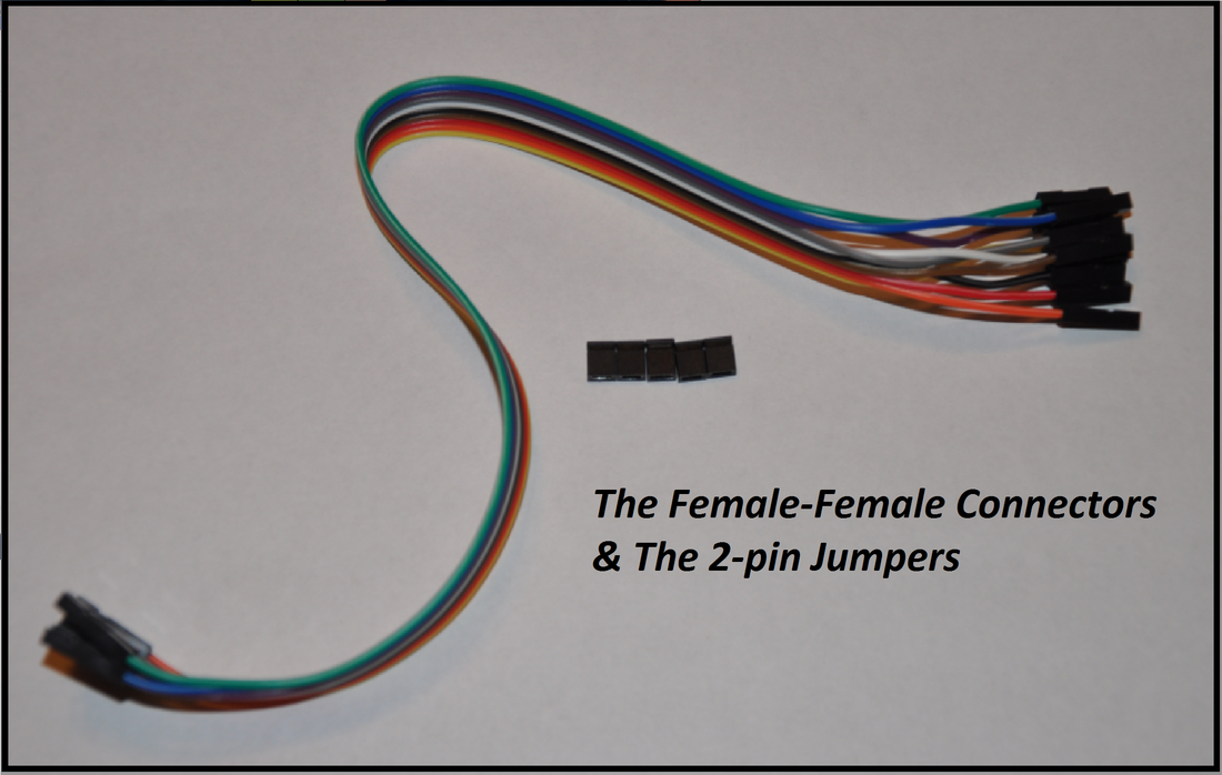
10x Female to female wire connectors
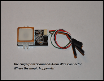
2x Fingerprint Scanner with connector cable
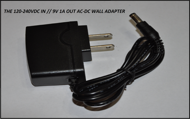
1x 120-240VAC 50/60Hz - 9v 1A AC-DC wall adapter
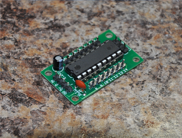
1x DIY port expander kit (Assembly video/manual below)
1x Link to all video and written manuals
How Do I Use It???
While this unit is extremely easy to use, we've created a written user manual, and several videos to showcase everything. The block diagrams in the written manual and the video above will make things much easier to understand, but I will go through basic functionality below. The written user manual is only available after purchase.
Starting up:
The version#2 board requires only a few connections prior to start up. Make sure that your fingerprint scanner modules are properly connected to the board. Double check your fingerprint scanner connections before you begin. When you power up, quickly ensure that both of the green power LEDs on the fingerprint scanner boards are lit up. If they do not light up, disconnect power immediately and check you connections!
Program Mode:
The programming mode for the Version#2 is a little less confusing than the programming mode for the version#1 board, but you have to pay close attention. There are three LEDs on the board. Make sure that you are aware of the names of each LED. There is the “PG” led, the “LE” LED, and the “RI” LED. PG = program LED, LE = left LED, and RI = right LED. Once you’ve tested your connections, remove power, Hold down the “SEL” button, and apply power. Make sure that you continue to hold the SEL button down. The PG/LE LEDs should light up. If you wish to program your left fingerprint scanner, then let go of the SEL button. If you wish to program the right fingerprint sensor, continue to hold the SEL button. After a couple of seconds, the LE LED should turn off, and the RI LED should turn on. Let go of the SEL Button. All LEDs should turn off for a moment, and then the PG LED should turn back on.
The fingerprint scanner that you’ve chosen will then light up. From here, you can choose which ID slot to save to. The program dictates that you can save up to 10x fingerprints to each sensor. Using any finger, press down onto the surface of the relative fingerprint scanner. The PG LED will flash once. After a moment, If you continue to hold your finger down on the surface of the sensor, the PG button will flash twice. After another moment you still continuing to hold, it will flash three times. This will continue all the way up until the PG LED flashes 10 times. This is how you choose ID slots. To save to ID slot#3, wait until the PG LED flashes three times, then let go. If you wish to save to slot#1, then let go as soon as the LED turns on when in this mode. If you wish to save to slot#6, wait for the LED to flash six times. Etc…Etc…
Once you’ve selected which ID slot to save to, the PG LED will turn on again once it is ready to receive a fingerprint. Place the finger that you wish to save onto the surface of the fingerprint scanner. Make sure that the finger is uniform with the surface each time you press it. Once you’ve pressed your finger down, after a moment, the PG LED will turn off. Take your finger off of the sensor. After a moment, the PG LED will turn back on. Place the same finger carefully back onto the sensor. After a moment, the PG LED will turn off. Remove your finger. Ready for the third and final scan? The PG LED will then turn back on. Place the same finger back onto the sensor for a third and final time. Once done, the PG LED will turn off. Remove your finger, and the PG button will flash for a few moments. This indicates that your fingerprint has been saved to the relative ID slot! Hurray! Now, power the unit down, and do the same thing again with a different finger on the other scanner. You need to remove power and follow these steps again every single time you want to save a new fingerprint.
Port Expander Assembly/Video Manuals:
Features:
1) Internal EEPROM memory saves fingerprint data after power off
2) Can Save Up To 10x unique fingerprints on each scanner
3) Easily enter into program mode or scanning mode
4) On-board relay control
5) Can directly power an Arduino UNO
6) Can be easily interfaced with the port expander board (Once assembled) to add 10x extra outputs to your project.
PLEASE SEE THE ABOVE VIDEO FOR A FULL DEMONSTRATION!
When you purchase this listing, you will receive the following:
1x Fully assembled and tested Version#2 project board
10x Female to female wire connectors
2x Fingerprint Scanner with connector cable
1x 120-240VAC 50/60Hz - 9v 1A AC-DC wall adapter
1x DIY port expander kit (Assembly video/manual below)
1x Link to all video and written manuals
How Do I Use It???
While this unit is extremely easy to use, we've created a written user manual, and several videos to showcase everything. The block diagrams in the written manual and the video above will make things much easier to understand, but I will go through basic functionality below. The written user manual is only available after purchase.
Starting up:
The version#2 board requires only a few connections prior to start up. Make sure that your fingerprint scanner modules are properly connected to the board. Double check your fingerprint scanner connections before you begin. When you power up, quickly ensure that both of the green power LEDs on the fingerprint scanner boards are lit up. If they do not light up, disconnect power immediately and check you connections!
Program Mode:
The programming mode for the Version#2 is a little less confusing than the programming mode for the version#1 board, but you have to pay close attention. There are three LEDs on the board. Make sure that you are aware of the names of each LED. There is the “PG” led, the “LE” LED, and the “RI” LED. PG = program LED, LE = left LED, and RI = right LED. Once you’ve tested your connections, remove power, Hold down the “SEL” button, and apply power. Make sure that you continue to hold the SEL button down. The PG/LE LEDs should light up. If you wish to program your left fingerprint scanner, then let go of the SEL button. If you wish to program the right fingerprint sensor, continue to hold the SEL button. After a couple of seconds, the LE LED should turn off, and the RI LED should turn on. Let go of the SEL Button. All LEDs should turn off for a moment, and then the PG LED should turn back on.
The fingerprint scanner that you’ve chosen will then light up. From here, you can choose which ID slot to save to. The program dictates that you can save up to 10x fingerprints to each sensor. Using any finger, press down onto the surface of the relative fingerprint scanner. The PG LED will flash once. After a moment, If you continue to hold your finger down on the surface of the sensor, the PG button will flash twice. After another moment you still continuing to hold, it will flash three times. This will continue all the way up until the PG LED flashes 10 times. This is how you choose ID slots. To save to ID slot#3, wait until the PG LED flashes three times, then let go. If you wish to save to slot#1, then let go as soon as the LED turns on when in this mode. If you wish to save to slot#6, wait for the LED to flash six times. Etc…Etc…
Once you’ve selected which ID slot to save to, the PG LED will turn on again once it is ready to receive a fingerprint. Place the finger that you wish to save onto the surface of the fingerprint scanner. Make sure that the finger is uniform with the surface each time you press it. Once you’ve pressed your finger down, after a moment, the PG LED will turn off. Take your finger off of the sensor. After a moment, the PG LED will turn back on. Place the same finger carefully back onto the sensor. After a moment, the PG LED will turn off. Remove your finger. Ready for the third and final scan? The PG LED will then turn back on. Place the same finger back onto the sensor for a third and final time. Once done, the PG LED will turn off. Remove your finger, and the PG button will flash for a few moments. This indicates that your fingerprint has been saved to the relative ID slot! Hurray! Now, power the unit down, and do the same thing again with a different finger on the other scanner. You need to remove power and follow these steps again every single time you want to save a new fingerprint.
Port Expander Assembly/Video Manuals:
|
|
|
|
|
|
|